Quote now
EN

Automotive air ducting systems direct heated or cooled air through a vehicle's HVAC system, helping maintain cabin comfort, distribute airflow, and manage ventilation across different interior zones. Depending on the vehicle design, air ducts may be installed behind the dashboard, inside the center console, beneath the seats, or along other interior structures.
Thermoforming offers a manufacturing option for selected automotive air duct components made from thermoplastic sheets. By heating a plastic sheet and shaping it against a mold, manufacturers can produce lightweight duct sections with defined contours, integrated bends, and geometries suited to available installation space. The process can also support customized designs and different production volumes, depending on the component's structure and performance requirements.
For automotive suppliers evaluating air ducting production methods, the right thermoforming solution depends on duct geometry, material properties, dimensional tolerances, airflow requirements, tooling design, and annual production targets. Understanding these factors helps manufacturers determine whether thermoforming is suitable for their air duct components and how to configure an efficient production process.
Thermoforming manufactures selected automotive air ducts by heating a thermoplastic sheet until it becomes formable, shaping it over or into a mold using vacuum, pressure, or mechanical assistance, and cooling it before removal. The formed component is then trimmed and inspected. Depending on the duct design, additional operations such as joining, sealing, drilling, or assembly may be required.
This process is suitable for certain duct panels, formed air passages, covers, transition sections, and other sheet-based components. The choice between thermoforming, injection molding, blow molding, and other manufacturing methods depends on the duct's cross-section, wall thickness, complexity, airtightness requirements, and production volume.
Thermoforming is a plastic manufacturing process in which a thermoplastic sheet is heated to a suitable forming temperature and shaped using a mold. Vacuum pressure, compressed air, mechanical plugs, or combinations of these methods can help the softened sheet conform to the required geometry. The material is subsequently cooled to retain its shape.
In automotive air ducting applications, thermoforming can produce components with curved surfaces, recessed sections, flanges, ribs, and other features supported by the mold and forming process. The resulting part may serve as a section of an air distribution channel or as a component that is joined with other molded or formed parts to create a complete duct assembly.
Unlike injection molding, which forms a part by injecting molten plastic into a closed mold, thermoforming starts with a premanufactured sheet. This distinction influences tooling design, material distribution, finishing operations, production cycle time, and the types of geometries that can be manufactured economically.
Not every automotive air duct is suitable for thermoforming. Small ducts with complex internal passages, intricate integrated connectors, or extensive three-dimensional features may be better suited to injection molding or another process. Manufacturers should evaluate the actual part design before selecting equipment.
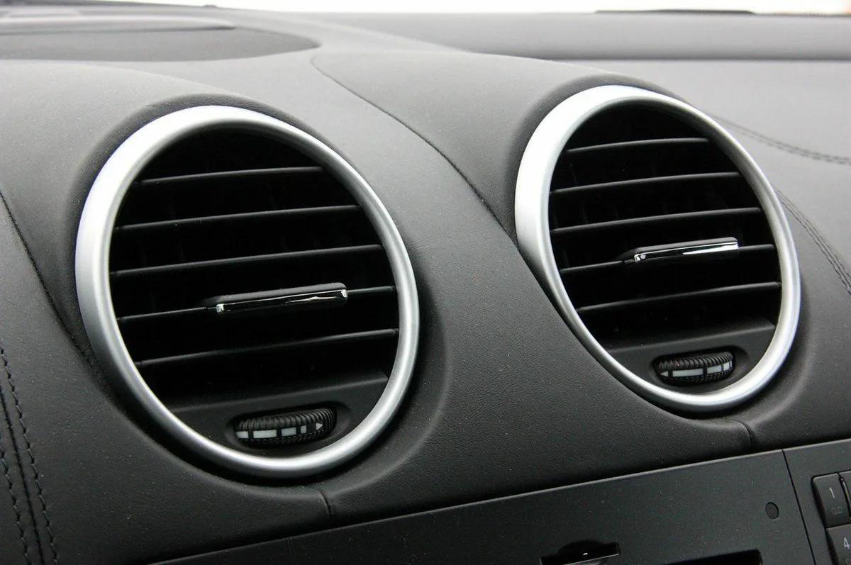
Automotive air duct components must fit within restricted interior spaces while maintaining their intended airflow paths. Thermoforming can offer several manufacturing advantages when the component geometry is compatible with sheet-based forming.
Vehicle manufacturers continually evaluate component weight because it affects vehicle efficiency, material usage, and assembly design. Thermoplastic air ducts can replace heavier alternatives in suitable applications, although the final weight depends on the selected resin, wall thickness, geometry, and reinforcement requirements.
Thermoforming can create shaped panels and duct sections without requiring the entire component to be machined from solid material. Material selection and thickness distribution should be optimized to achieve the required stiffness without unnecessary weight.
Automotive HVAC systems must accommodate dashboard structures, instrument panels, electronic modules, wiring harnesses, and other components. Air ducts therefore need carefully designed bends, transitions, mounting features, and connection points.
Thermoforming can support a range of curved and contoured surfaces. Mold modifications may also be more practical than developing entirely new tooling for certain design changes, depending on the mold construction and the extent of the revision.
However, the process has geometric limits. Deep draws, sharp corners, narrow channels, and complex undercuts can create forming difficulties or require additional tooling features and secondary assembly.
Thermoforming may be attractive for prototype development, pilot production, aftermarket components, and selected production programs where its tooling and processing costs compare favorably with alternatives.
Tooling economics depend on part size, mold material, surface finish, heating requirements, automation, and expected output. Injection molding may offer better unit economics for some high-volume components, particularly when the design includes intricate integrated features.
Manufacturers should compare total production costs rather than assuming that one process is always less expensive.
A thermoforming machine can be configured with sheet loading, heating, forming, cooling, unloading, trimming, and inspection operations. Depending on the required output, manufacturers may choose manual, semi-automatic, or automated handling.
Integration with existing production systems can help reduce material handling and improve process consistency. The equipment layout should account for mold changes, trimming stations, scrap removal, operator access, and inspection requirements.
The suitability of thermoforming depends on the geometry and function of each part. Some air ducting components are well suited to sheet forming, while others require alternative processes or a combination of manufacturing methods.
| Automotive air duct component | Potential thermoforming application | Main design consideration |
|---|---|---|
| HVAC duct panels | Formed panels that create part of an air passage | Contour accuracy and joining interfaces |
| Air distribution channel sections | Shaped sections assembled into a duct | Cross-sectional consistency and airflow |
| Dashboard air passage components | Contoured sections routed behind the instrument panel | Space constraints and mounting points |
| Under-seat air duct sections | Low-profile formed channels | Packaging space and mechanical durability |
| Air duct covers | Protective or enclosing panels | Fit, stiffness, and surface quality |
| Transition sections | Components connecting different duct shapes | Smooth transitions and dimensional control |
| Custom ventilation housings | Sheet-formed shells or covers where geometry permits | Draw depth, flanges, and assembly design |
These applications are examples rather than a universal list of thermoformable parts. A complete duct assembly may combine thermoformed sections with injection-molded connectors, flexible hoses, seals, or other components.
Material selection affects formability, stiffness, temperature resistance, chemical compatibility, noise behavior, durability, and cost. The resin must meet the requirements of its intended position within the vehicle.
Polypropylene is used in various automotive interior and air management components because of its low density, chemical resistance, and availability in different grades. Selected PP sheet formulations can be thermoformed into suitable duct panels and other shaped parts.
Its performance depends on grade, additives, sheet structure, and processing conditions. Manufacturers should verify heat resistance, stiffness, impact performance, and dimensional stability under the intended operating conditions.
ABS offers a useful combination of rigidity, impact performance, and surface quality in suitable grades. It can be considered for certain formed housings, covers, and duct-related components where its temperature and environmental limits are acceptable.
Because automotive HVAC components may experience warm air, cold air, vibration, and repeated temperature changes, the selected ABS grade must be checked against the component's service environment.
Polycarbonate and selected PC blends may be considered when an application requires particular impact or thermal properties. Their suitability depends on the specific formulation, forming conditions, cost target, and operating environment.
They are not automatically preferable to PP or ABS. The engineering team should compare the required mechanical properties and processing behavior before choosing a sheet material.
Selected thermoplastic elastomers (TPEs) can provide flexibility for components that need compliant sections or specific sealing behavior. However, their stiffness, heat resistance, creep behavior, and forming characteristics vary significantly between formulations.
A flexible duct section may require different design and processing considerations from a rigid duct panel. Material compatibility should be confirmed through testing rather than assumed from the general resin category.
| Material | Potential advantages | Points to evaluate |
|---|---|---|
| PP | Low density, chemical resistance, broad automotive use | Heat resistance, stiffness, shrinkage, and impact performance |
| ABS | Rigidity, impact properties, surface finish | Temperature limits, chemical exposure, and grade suitability |
| PC or PC blends | Potential impact and thermal performance benefits | Cost, forming window, environmental compatibility, and grade |
| Selected TPE grades | Flexibility and compliant behavior | Creep, dimensional stability, temperature resistance, and sealing needs |
For automotive air ducting, material selection should consider the entire service environment, including temperature cycling, exposure to cleaning agents, vibration, aging, and any relevant OEM specifications.
A consistent manufacturing process begins with the part specification and continues through sheet preparation, forming, finishing, and inspection. Each stage influences the quality of the finished duct.
The process begins with a three-dimensional model or engineering drawing that defines the duct's shape, dimensions, wall thickness requirements, interfaces, and mounting features.
Design engineers should evaluate draft angles, corner radii, draw depth, material stretching, and the location of trimming lines. A geometry that is easy to manufacture in injection molding may need modification before it can be formed successfully from a flat sheet.
The mold must also account for material shrinkage, cooling behavior, surface finish, and any vacuum or pressure connections. Prototypes and forming trials can reveal areas where the sheet stretches excessively or fails to reproduce the intended contour.
The selected plastic sheet is inspected for thickness consistency, surface defects, contamination, and suitability for the forming process.
Sheet dimensions and placement must match the machine's forming area and clamping arrangement. Where the material is moisture-sensitive or subject to specific storage requirements, the supplier's handling instructions should be followed.
Consistent incoming material helps reduce variation in forming behavior and finished-part dimensions.
The sheet is heated until it reaches a temperature range suitable for the selected material. Heating systems may use infrared elements, ceramic heaters, or other configurations designed for the machine and sheet type.
Uniform heating is important because different areas of the sheet stretch at different rates during forming. If one area is too cold, it may resist forming or produce surface defects. If another area is overheated, the material may sag excessively, thin out, or degrade.
Heating time and temperature settings should be established through trials for the actual sheet grade, thickness, color, and machine configuration.
Once the sheet reaches its forming window, it is moved into contact with the mold. Vacuum forming uses reduced pressure to draw the sheet against the mold surface. Pressure forming applies compressed air to help shape the material, while plug-assisted forming uses a mechanical tool to improve material distribution in selected geometries.
The appropriate method depends on the required surface detail, draw depth, dimensional tolerances, and material characteristics.
For automotive air ducting, mold design should support the required cross-section and joining geometry. Features that create excessive stretching or trap air may require changes to the mold, venting, heating profile, or forming sequence.
After forming, the plastic must cool sufficiently to retain its shape during removal. Cooling may occur through the mold, controlled air circulation, or other arrangements appropriate to the machine and component.
Removing a part before it has stabilized can lead to warping, distortion, or dimensional changes. Excessively long cooling periods, on the other hand, can reduce production output.
The process should balance cooling time with dimensional stability and the material's thermal behavior.
The formed sheet often contains excess material around the component. Trimming removes this material and establishes the final outline, openings, and connection edges.
Depending on the design, additional operations may include drilling, machining, joining two formed halves, installing connectors, or adding seals. The trimming method may be manual, fixture-based, CNC-controlled, or integrated into an automated production line.
Trim accuracy is especially important at mating surfaces, where gaps or misalignment may affect assembly and airflow performance.
Finished air duct components should be checked against the drawing and performance requirements. Inspection may include dimensional measurement, visual checks, thickness mapping, fit verification, and assembly trials.
Where appropriate, functional testing can evaluate leakage, airflow resistance, pressure loss, or other application-specific characteristics. The actual test method and acceptance limits should come from the component specification or customer requirements.
A documented inspection process helps manufacturers identify recurring defects and adjust heating, forming, cooling, or trimming parameters.
Vacuum forming and pressure forming are both used for thermoplastic sheet forming, but they do not produce identical results in every application.
Vacuum forming relies on a pressure difference to draw the heated sheet against the mold. Pressure forming adds compressed air to increase the force applied to the sheet. The best method depends on the material, mold design, desired surface detail, geometry, and production target.
| Comparison factor | Vacuum forming | Pressure forming |
|---|---|---|
| Forming mechanism | Vacuum draws the sheet against the mold | Compressed air assists sheet conformity to the mold |
| Surface detail | Suitable for many functional contours | Can support finer detail when the material and mold permit |
| Equipment configuration | Requires suitable vacuum generation and control | Requires pressure capability in addition to appropriate forming controls |
| Tooling requirements | Depends on part geometry and mold construction | May require tooling designed to withstand the applied pressure |
| Application fit | Suitable for many relatively straightforward formed parts | Worth evaluating when greater detail or more demanding surface reproduction is needed |
| Cost considerations | Depends on machine, tooling, and cycle requirements | May involve additional equipment and tooling costs |
Neither method automatically guarantees uniform wall thickness, accurate dimensions, or leak-free ducts. Those outcomes depend on the complete process, including sheet properties, heating, mold geometry, forming parameters, cooling, and finishing.
Thermoforming and injection molding serve different manufacturing needs. Comparing them early in the design process can help avoid selecting equipment that does not match the component.
| Factor | Thermoforming | Injection molding |
|---|---|---|
| Starting material | Thermoplastic sheet | Plastic resin, typically pellets |
| Forming method | Heated sheet shaped against a mold | Molten plastic injected into a closed mold |
| Tooling economics | May be attractive for selected designs and production volumes | Mold costs can be higher, but may be offset by large production runs |
| Geometry | Suited to sheet-based contours and formed shells | Can produce complex integrated features within process limits |
| Wall thickness | Varies with sheet stretching | Controlled through part and mold design, packing, and processing |
| Secondary operations | Trimming is often required; joining may be needed | Gates and runners may require removal; assembly depends on design |
| Production rate | Depends on heating, forming, cooling, and finishing | Often suited to high-volume repeat production |
| Best-fit applications | Selected panels, shells, channels, and custom formed parts | Complex ducts, integrated connectors, and high-volume components |
For a duct requiring complicated internal passages or numerous integrated features, injection molding may be the more practical choice. Thermoforming may be suitable for simpler sheet-based geometries, larger formed sections, or components where the tooling and production economics are favorable.
A cost comparison should include tooling, machine investment, labor, cycle time, material utilization, scrap, trimming, joining, inspection, and maintenance.
Selecting equipment starts with the part rather than the machine's advertised capacity. A suitable system must accommodate the sheet material, forming area, mold geometry, required quality, and expected production output.
The machine's usable forming area must accommodate the sheet size and the layout of the part or parts on the sheet. The clamping system and mold interface must also suit the planned tooling.
For larger duct components, manufacturers should check the available forming depth, mold clearance, loading space, and part removal method.
The heating system should provide a controllable temperature profile across the sheet. Different materials and sheet thicknesses may require different heater arrangements and cycle settings.
Independent heater zones can help operators adjust heat distribution to match the geometry. However, the actual performance depends on heater layout, controls, sheet positioning, and process validation.
The machine should provide the forming method required by the part. Depending on the application, this may involve vacuum forming, pressure forming, mechanical plug assistance, or a combination of techniques.
Manufacturers should confirm the available operating range, control repeatability, mold compatibility, and service requirements before purchasing equipment.
Automation options may include sheet loading, mold movement, part unloading, trimming, stacking, and production monitoring. These features can reduce repetitive handling and improve process consistency when configured for the component.
Production capacity should be evaluated using the complete cycle, not only the forming stage. Heating, cooling, trimming, inspection, mold changes, and downstream assembly can all limit actual output.
Suppliers manufacturing several duct designs may need frequent mold changes. The equipment should allow practical access for tool installation, secure mold mounting, and repeatable setup.
If the production program includes multiple materials or sheet thicknesses, the control system and heating arrangement should support the required process adjustments.
A machine purchase should also account for spare parts, service access, operator training, maintenance requirements, and technical support. These factors influence long-term operating costs and production uptime.
Before committing to a machine, manufacturers should provide the supplier with representative part drawings, material specifications, production targets, and quality requirements. A sample-forming trial can help verify whether the proposed equipment meets the actual application needs.
Defects in thermoformed air duct components can affect assembly, dimensions, surface appearance, and functional performance. The causes should be investigated systematically rather than corrected through isolated parameter changes.
Uneven thickness can result from nonuniform heating, excessive local stretching, unsuitable mold geometry, or insufficient material distribution.
Possible corrective measures include adjusting heater zones, reviewing the draw ratio, modifying radii, and evaluating plug assistance where appropriate. Thickness measurements across representative areas can help identify where material is being stretched excessively.
Wrinkles or webbing can occur when material folds or bridges between nearby mold features instead of following the intended surface.
Potential causes include unsuitable sheet positioning, excessive material slack, incorrect heating, or poor mold geometry. Changes to the mold layout, sheet clamping, heating profile, or forming sequence may reduce the problem.
Warpage can develop when the part cools unevenly, is released before it has stabilized, or experiences residual stresses during forming.
Manufacturers can review mold temperature, cooling time, part support, and the consistency of the forming cycle. Measurements should be taken after the part has reached a defined and repeatable inspection condition.
Surface defects may arise from contamination, unsuitable mold finish, insufficient sheet heating, trapped air, or inconsistent material quality.
Maintaining clean tooling, verifying sheet condition, and checking mold venting can help improve surface reproduction. The required surface quality should be defined according to the component's function and visibility.
A thermoformed part may have correct dimensions yet still leak when assembled into a complete air duct. Leakage can originate from poor trimming, misaligned mating surfaces, inadequate seals, or inconsistent joining.
The solution may involve tighter dimensional controls, revised fixtures, better sealing design, or a validated joining process. Functional testing of the assembled duct is more informative than relying on visual inspection alone.
Quality requirements should be established from the component drawing, vehicle program, and customer specification. A part's appearance alone does not establish whether it will perform correctly in an HVAC system.
Dimensional inspection checks the duct's overall shape, connection interfaces, mounting locations, and fit within the available vehicle space. Thickness inspection helps identify excessive stretching or local weakness.
Functional evaluation may include airflow measurement, pressure drop, leakage testing, vibration resistance, and temperature cycling where required by the application. Material testing may cover impact performance, aging, chemical exposure, odor, or emissions if those properties are specified.
The appropriate test plan depends on the duct's location, operating conditions, regulatory obligations, and OEM requirements. Manufacturers should avoid applying generic acceptance limits where the customer has defined specific criteria.
For driver-side or passenger-side components located near footwells, the complete assembly should also be checked for clearance from pedals, wiring, moving parts, and other nearby equipment. Retention and installation features should match the vehicle's requirements.
Production efficiency depends on the entire manufacturing system rather than a single machine setting.
A stable heating profile can reduce forming variation and the need for rework. Appropriate mold design can improve material distribution and reduce difficult trimming operations. Optimized cooling can shorten the cycle while maintaining dimensional stability.
Material nesting and sheet layout can improve material utilization, particularly when multiple components can be formed from a common sheet. However, the layout must preserve adequate clamping areas and avoid compromising the part's forming quality.
Automation may reduce handling time and improve repeatability, but it should be matched to the production volume and product mix. A highly automated line may not be economical for a low-volume program with frequent design changes.
Manufacturers should monitor measurable production indicators such as cycle time, scrap rate, first-pass yield, material utilization, unplanned downtime, and the frequency of mold changes. These measurements help identify whether the main opportunity lies in heating, forming, trimming, material handling, or quality control.
Automotive air ducting is the network of passages and components that directs conditioned air from a vehicle's HVAC system to vents and other delivery points. Ducts may be located behind the dashboard, inside the center console, beneath seats, or elsewhere in the vehicle interior.
Yes. Thermoforming can manufacture selected air duct panels, formed channels, transition sections, covers, and housings from compatible thermoplastic sheets. Suitability depends on the geometry, required wall thickness, joining method, dimensional tolerances, and functional performance.
Depending on the application, suitable materials may include polypropylene, ABS, selected polycarbonate blends, and certain thermoplastic elastomers. The specific grade should be selected according to temperature resistance, stiffness, impact performance, chemical exposure, formability, and customer requirements.
Neither is universally better. Vacuum forming may suit many functional sheet-based components, while pressure forming can help reproduce more detailed surfaces in appropriate applications. The decision should be based on the part geometry, surface requirements, material, tooling, and production economics.
Thermoforming can produce many curved surfaces, flanges, recesses, and transitions. Deep draws, sharp corners, undercuts, and complex internal passages may require specialized tooling, multiple formed components, secondary joining, or a different manufacturing process.
Thermoforming shapes a heated plastic sheet and commonly requires trimming after forming. Injection molding injects molten plastic into a closed mold and can support more complex integrated features. The most suitable process depends on design complexity, tooling costs, annual volume, cycle time, and assembly requirements.
They can review heater-zone settings, sheet positioning, forming depth, mold radii, and material distribution. Plug assistance or mold redesign may help in selected applications. Thickness mapping during process trials can identify areas that need adjustment.
Leakage can result from poorly aligned joints, inaccurate trimming, unsuitable sealing features, inconsistent joining, or dimensional variation. Manufacturers should evaluate the assembled duct using the specified leakage or airflow test rather than relying only on individual-part inspection.
Buyers should evaluate forming area, material compatibility, heating uniformity, vacuum or pressure capability, mold interface, automation, trimming requirements, production throughput, maintenance, and technical support. Representative part drawings and production targets help suppliers recommend an appropriate configuration.
It can be suitable for selected high-volume components when cycle time, tooling, material utilization, and quality requirements support the business case. Injection molding may be more economical for some high-volume, complex duct designs. A total-cost analysis and production trial provide a stronger basis for choosing.
Depending on the specification, testing may include dimensional checks, wall thickness measurement, fit verification, airflow and pressure-drop evaluation, leakage testing, temperature cycling, vibration resistance, and material durability checks.
Yes, if the machine's forming area, heating system, mold interface, and process capabilities accommodate the different parts. Each design may require its own mold, process settings, and validation. Frequent mold changes should be included in production planning.
Thermoforming provides a practical manufacturing option for selected automotive air ducting components that can be formed from thermoplastic sheets. It supports a range of shaped panels, duct sections, covers, and transition components, provided the design is compatible with the forming process and the finished parts meet the required functional specifications.
Successful production depends on material selection, mold design, controlled heating, appropriate forming methods, stable cooling, accurate trimming, and verification of the assembled duct. Manufacturers should also consider whether thermoforming offers the right balance of tooling investment, production speed, material utilization, and design flexibility compared with injection molding or other alternatives.
For automotive suppliers evaluating thermoforming equipment, the best starting point is a representative component drawing, the intended material, the target production volume, and a clear set of dimensional and functional requirements. These details help equipment suppliers recommend a system that matches the real manufacturing task rather than relying on machine capacity alone.